
Notice
Recent Posts
Recent Comments
Link
| 일 | 월 | 화 | 수 | 목 | 금 | 토 |
|---|---|---|---|---|---|---|
| 1 | ||||||
| 2 | 3 | 4 | 5 | 6 | 7 | 8 |
| 9 | 10 | 11 | 12 | 13 | 14 | 15 |
| 16 | 17 | 18 | 19 | 20 | 21 | 22 |
| 23 | 24 | 25 | 26 | 27 | 28 |
Tags
- prescaling
- Linked List
- Algorithm
- java
- i2c 통신
- test bench
- half adder
- vivado
- stop watch
- DHT11
- hc-sr04
- ATMEGA128A
- ring counter
- uart 통신
- behavioral modeling
- KEYPAD
- D Flip Flop
- gpio
- Recursion
- Edge Detector
- dataflow modeling
- structural modeling
- FND
- pwm
- Pspice
- soc 설계
- verilog
- LED
- atmega 128a
- BASYS3
Archives
- Today
- Total
거북이처럼 천천히
Verilog RTL 설계(7월 31일 - 3, PWM - 3) 본문
1. LED의 밝기를 128단계로 나누어 컨트롤하기.
- 이번에는 LED의 밝기를 128단계로 나누어 컨트롤 할 수 있도록 모듈 설계해보도록 하겠다.
- 이를 통해 "왜 2단계로 나누어 Prescaling을 진행하는가?"를 정확하게 이해 할 수 있다.
< Source, LED의 밝기를 128단계로 나누기 위해 Duty ratio를 128단계로 나누어 컨트롤하는 모듈 >
// Duty ratio 128 step Control
module pwm_led_128_step(
    input clk, reset_p,
    input [6:0] duty,
    output pwm);

    // Declare base parameter
    parameter sys_clk = 100_000_000;
    parameter pwm_freq = 10_000;
    parameter duty_step = 128;

    // 최종적으로 10kHz Pulse를 만들기 위한 prescaling 만들기.
    parameter temp = sys_clk / pwm_freq / duty_step;
    parameter temp_half = temp / 2;


    // 10kHz Pulse wave를 만들기 위한 Prscaling
    reg [6:0] cnt_sysclk;

    always @(posedge clk or posedge reset_p) begin
        if(reset_p) cnt_sysclk = 0;
        else begin
            if(cnt_sysclk >= temp - 1) cnt_sysclk = 0;
            else cnt_sysclk = cnt_sysclk + 1;
        end
    end

    wire pwm_freqX128;
    assign pwm_freqX128 = (cnt_sysclk < temp_half)? 0 : 1;

    wire pwm_freqX128_nedge;
    edge_detector_p edge_detector_0 (.clk(clk), .reset_p(reset_p), .cp(pwm_freqX128), .n_edge(pwm_freqX128_nedge));

    // PWM의 Duty ratio을 128단계로 나누어 컨트롤 하기 위해서
    // 따라서 128로 분주화하는 것이다.
    reg [6:0] cnt_pwm;

    always @(posedge clk or posedge reset_p) begin
        if(reset_p) cnt_pwm = 0;
        else if(pwm_freqX128_nedge) cnt_pwm = cnt_pwm + 1;
    end

    assign pwm = (cnt_pwm < duty)? 1 : 0;

endmodule

// Edge detector
module edge_detector_p (
    input clk, reset_p,
    input cp,
    output n_edge, p_edge );

    reg flip_flop_current, flip_flop_old;


    always @(posedge clk or posedge reset_p) begin
        if(reset_p) begin
            flip_flop_current <= 0;
            flip_flop_old <= 0;
        end
        else begin
            flip_flop_current <= cp;
            flip_flop_old <= flip_flop_current;
        end
    end

    assign p_edge = ({flip_flop_current, flip_flop_old} == 2'b10)? 1 : 0;
    assign n_edge = ({flip_flop_current, flip_flop_old} == 2'b01)? 1 : 0;

endmodule- 선언한 3개의 parameter는 다음과 같은 의미를 같는다.
- sys_clk : 10ns인 Clock Pulse의 주파수
- pwm_freq : LED가 연속적으로 나오기 위한 주파수 , 10kHz
- duty_step : duty ratio를 128단계로 나눈다는 정보를 담고 있는 parameter
★ ★ ★ ★ ★ ★ ★ ★ ★ ★ ★ ★ ★ - Q) 아래 코드에서 왜 아래와 같은 공식 나왔는가?
parameter temp = sys_clk / pwm_freq / duty_step;- A) 이는 prescaling을 두 번으로 나누어 시행한 이유와도 연관 있다. 먼저, PWM의 duty ratio을 몇 단계로 나눌지 여부를 결정한다. 그리고, 난 뒤, Clock Pulse를 duty_step만큼 prescaling한다. 이렇게 prescaling을 통해 생성된 새로운 Pulse wave는 100000000Hz / duty_step 만큼의 주파수를 갖는다.
하지만, 우리가 원하는 Pulse wave는 10000Hz를 가져야 하기 때문에 100000000Hz / duty_step 만큼의 주파수를 갖는 펄스파를 몇 분주해야 10000Hz Pulse wave로 만들 수 있는가?
바로, 100000000Hz / duty_step / 10000 만큼 Prescaling을 해야 분주화를 통해 10000Hz Pulse wave를 얻을 수 있다. 따라서 위 식은 이러한 과정을 통해 얻었으며, 이는 "왜 2번의 Prescaling을 해야하는가?"에 대한 질문의 해답이라고 할 수 있다. - 첫 번째, Prescaling은 10000Hz pulse wave를 만들기 위함의 Prescaling이며,
두 번째, Prescaling은 Pulse wave의 duty ratio를 단계별로 나누어 컨트롤하기 위한 Prescaling이다.
< Source, Period = 100usec, Duty ratio의 step = 128인 PWM을 control하는 Top Module >
// Duty ratio 128 step Control top module
module pwm_led_128_step_top_module (
    input clk, reset_p,
    input [6:0] duty,
    output pwm);

     pwm_led_128_step pwm_module(.clk(clk), .reset_p(reset_p), .duty(duty), .pwm(pwm));

endmodule
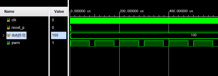
< Simulation, Duty ratio = 100 >
< Simulation, Duty ratio = 50 >

< Simulation, Duty ratio = 120 >

'RTL Design > Verilog RTL 설계' 카테고리의 다른 글
| Verilog RTL 설계(8월 1일 - 1, PWM - 5) (0) | 2024.08.02 |
|---|---|
| Verilog RTL 설계(7월 31일 - 4, PWM - 4) (0) | 2024.08.01 |
| Verilog RTL 설계(7월 31일 - 2, PWM - 2) (0) | 2024.08.01 |
| Verilog RTL 설계(7월 31일 - 1, PWM - 1) (0) | 2024.08.01 |
| Verilog RTL 설계(7월 22일 - 3, 4X4 Matrix Keyboard - 3) (0) | 2024.07.25 |
'RTL Design/Verilog RTL 설계' Related Articles
more


