
Notice
Recent Posts
Recent Comments
Link
| 일 | 월 | 화 | 수 | 목 | 금 | 토 |
|---|---|---|---|---|---|---|
| 1 | 2 | 3 | ||||
| 4 | 5 | 6 | 7 | 8 | 9 | 10 |
| 11 | 12 | 13 | 14 | 15 | 16 | 17 |
| 18 | 19 | 20 | 21 | 22 | 23 | 24 |
| 25 | 26 | 27 | 28 | 29 | 30 | 31 |
Tags
- test bench
- atmega 128a
- LED
- half adder
- Algorithm
- prescaling
- vivado
- Recursion
- soc 설계
- Linked List
- Pspice
- pwm
- structural modeling
- BASYS3
- ATMEGA128A
- DHT11
- verilog
- uart 통신
- behavioral modeling
- dataflow modeling
- ring counter
- gpio
- KEYPAD
- D Flip Flop
- Edge Detector
- FND
- java
- stop watch
- i2c 통신
- hc-sr04
Archives
- Today
- Total
거북이처럼 천천히
Verilog RTL 설계(7월 23일 - 3, DHT11 구현 (2) ) 본문
1. Top module of DHT11
- 이전 게시글에서 구현한 dht11_cntr module를 실행시키기 위해 top module를 만들어서 실행해보도록 하겠다.
- dht11_cntr module 에 대한 게시글은 아래 링크를 참고하길 바란다.
https://jbhdeve.tistory.com/295
Verilog RTL 설계(7월 23일 - 2, DHT11 구현 (1) )
1. State diagram of dht11 Sensor ModuleMCU와 DHT 11 모듈 간에 통신 과정을 State diagram으로 그린다면 다음과 같이 표현할 수 있다. 2. DHT11로부터 온도, 습도 데이터 받아 Basys3의 FND로 출력DHT11로부터 데
jbhdeve.tistory.com
< Source, Top module of DHT11 >
// Top module
module top_module_dht11 (
    input clk, reset_p,
    inout dht11_data,
    output [3:0] com,
    output [7:0] seg_7,
    output [5:0] led_state );

    wire [7:0] temperature, humidity;
    dht11_cntr control_dht11 (.clk(clk), .reset_p(reset_p), .dht11_data(dht11_data),
                .temperature(temperature), .humidity(humidity), .led_state(led_state));

    // FND Control
    wire [15:0] hex_value;
    assign hex_value = {temperature, humidity};

    fnd_cntr fnd_control (.clk(clk), .reset_p(reset_p), .hex_value(hex_value), .com(com), .seg_7(seg_7));
endmodule
< 구현 >
- FND의 앞 두자리는 온도, 뒤 두자리는 습도이기 때문에 해당 공간의 온도와 습도는 다음과 같다.
- Temperature : 1A = 26
- Humidty : 29

2. Convert from Binary to Decimal
- FND를 통한 온도, 습도 데이터 출력이 16진수 형태로 출력되기 때문에 보다 이해하기 쉽게 BCD 코드로 변환하도록 하겠다.
- 2진수에서 BCD 코드로 변환하기 위해 Double Dabble 알고리즘을 사용하도록 하겠다.
- Double Dabble 알고리즘에 대한 이론 설명은 아래 게시글을 참고하길 바란다.
https://jbhdeve.tistory.com/294
Algorithm - Double Dabble
1. 빠르게 2진수에서 10진수로 변환할 수 있는 방법은 없는가?2진수로 표현된 숫자들을 16진수로 변환하는 과정은 굉장히 쉽다.아래 표처럼 2진수를 4자리씩 끊어서 16진수로 변환할 수 있다.2진수1
jbhdeve.tistory.com
< Source, Convert from Binary to Decimal >
module bin_to_dec(
        input [11:0] bin,
        output reg [15:0] bcd
    );

    reg [3:0] i;

    always @(bin) begin
        bcd = 0;
        for (i=0;i<12;i=i+1)begin
            bcd = {bcd[14:0], bin[11-i]};
            if(i < 11 && bcd[3:0] > 4) bcd[3:0] = bcd[3:0] + 3;
            if(i < 11 && bcd[7:4] > 4) bcd[7:4] = bcd[7:4] + 3;
            if(i < 11 && bcd[11:8] > 4) bcd[11:8] = bcd[11:8] + 3;
            if(i < 11 && bcd[15:12] > 4) bcd[15:12] = bcd[15:12] + 3;
        end
    end
endmodule
< Source, 온도 습도 데이터를 BCD 형태로 출력하는 Top Module >
// Top module
module top_module_dht11 (
    input clk, reset_p,
    inout dht11_data,
    output [3:0] com,
    output [7:0] seg_7,
    output [5:0] led_state );

    wire [7:0] temperature, humidity;
    dht11_cntr control_dht11 (.clk(clk), .reset_p(reset_p), .dht11_data(dht11_data), .temperature(temperature), .humidity(humidity), .led_state(led_state));

    // Convert from binary to decimal
    wire [15:0] temperature_bcd, humidity_bcd;
    bin_to_dec convert_temperature(.bin({4'b0, temperature}), .bcd(temperature_bcd));
    bin_to_dec convert_humidity(.bin({4'b0, humidity}), .bcd(humidity_bcd));

    // FND Control
    wire [15:0] hex_value;
    assign hex_value = {temperature_bcd[7:0], humidity_bcd[7:0]};

    fnd_cntr fnd_control (.clk(clk), .reset_p(reset_p), .hex_value(hex_value), .com(com), .seg_7(seg_7));
endmodule
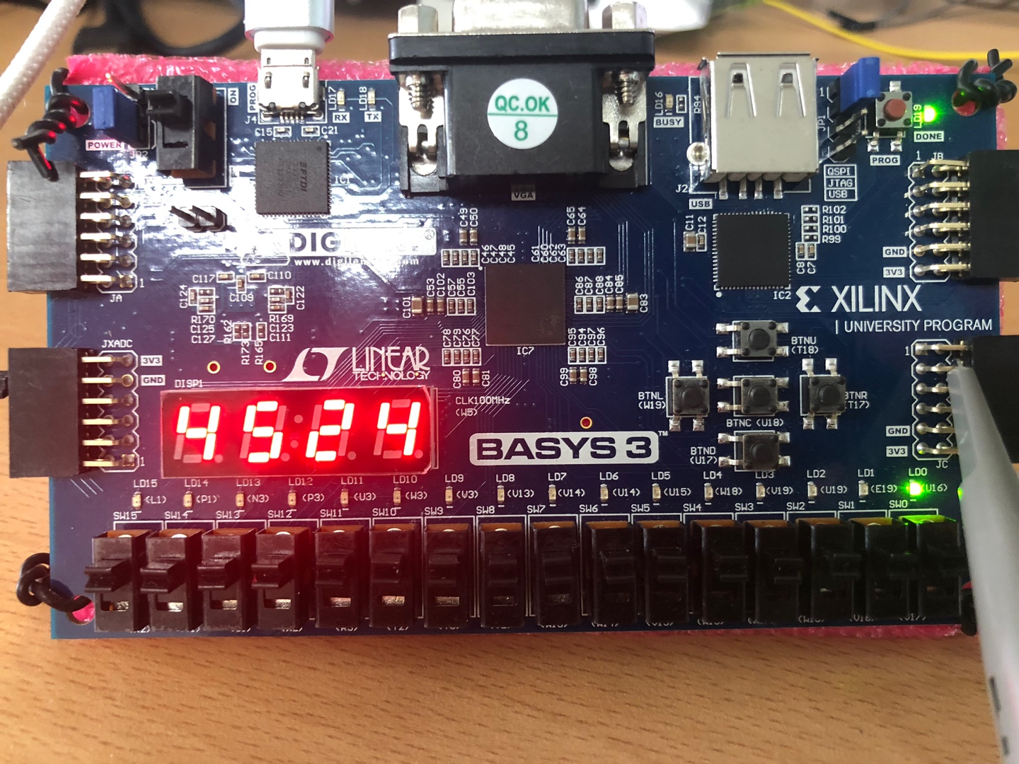
< 구현 >
- FND에 출력되는 BCD로 변환된 온습도 데이터를 통해 습도는 45, 온도는 24임을 확인하였다.
< 오실로스코프를 통한 DHT11과 Basys3간에 통신 >
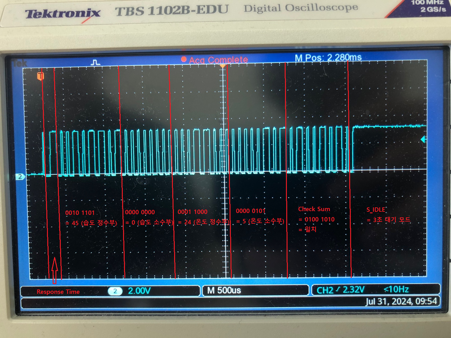
- 오실로스코프를 dht11_data 단자와 연결하여 위와 같은 파형을 얻을 수 있었으며, 위 파형은 DHT11과 Basys3간에 통신 신호를 나타내고 있다.
- 온도, 습도 데이터의 정수부, 소수부를 얻은 뒤, check sum과 비교한 결과, 전송간에 데이터 손실이 발생하지 않았음을 확인하였고, 손실이 발생하지 않았음을 확인후, 온도, 습도 데이터를 FND로 출력하였다.
'RTL Design > Verilog RTL 설계' 카테고리의 다른 글
| Verilog RTL 설계(8월 1일 - 2, PWM을 통한 Motor 제어 - 1) (0) | 2024.08.12 |
|---|---|
| Verilog RTL 설계(7월 23일 - 4, DHT11 구현 (3) ) (0) | 2024.08.10 |
| Verilog RTL 설계(7월 23일 - 2, DHT11 구현 (1) ) (0) | 2024.08.10 |
| Verilog RTL 설계(7월 19일 - 2, Cooking Timer - 2) (0) | 2024.08.08 |
| Verilog RTL 설계(7월 19일 - 1, Cooking Timer - 1) (0) | 2024.08.08 |
'RTL Design/Verilog RTL 설계' Related Articles
more


