
Notice
Recent Posts
Recent Comments
Link
| 일 | 월 | 화 | 수 | 목 | 금 | 토 |
|---|---|---|---|---|---|---|
| 1 | ||||||
| 2 | 3 | 4 | 5 | 6 | 7 | 8 |
| 9 | 10 | 11 | 12 | 13 | 14 | 15 |
| 16 | 17 | 18 | 19 | 20 | 21 | 22 |
| 23 | 24 | 25 | 26 | 27 | 28 | 29 |
| 30 |
Tags
- stop watch
- Pspice
- LED
- Linked List
- pwm
- soc 설계
- ring counter
- FND
- Recursion
- Algorithm
- KEYPAD
- java
- Edge Detector
- D Flip Flop
- behavioral modeling
- hc-sr04
- dataflow modeling
- ATMEGA128A
- vivado
- structural modeling
- BASYS3
- DHT11
- i2c 통신
- prescaling
- half adder
- atmega 128a
- test bench
- uart 통신
- verilog
- gpio
Archives
- Today
- Total
거북이처럼 천천히
10kHz인 PWM 설계 (Duty ratio stage 100단계) - (1) 본문
1. Duty ratio를 100단계로 나눈 10kHz PWM 설계
- Clock Pulse (Period = 10ns)를 100분주화를 2번하여 10kHz PWM을 설계하도록 하겠다.
- 해당 PWM은 Duty ratio를 총 100단계로 나누어 원하는 duty ratio를 갖는 PWM을 만들 수 있다.
- 소스 코드 및 PWM에 대한 자세한 설명은 아래 게시글을 참고하길 바란다.
https://jbhdeve.tistory.com/283
Verilog RTL 설계(7월 31일 - 2, PWM - 2)
1. 다이오드가 연속적으로 켜져 있는 상태로 보이기 위해서는 10kHz Pulse wave를 줘야 한다.다이오드가 사람 눈으로 보았을 때, 연속적으로 켜져 있는 상태로 보여주기 위해서는 10kHz 주파수를 갖는
jbhdeve.tistory.com
2. 소스 코드
< Source, Edge detector >
// Edge detector
module edge_detector (
    input clk, reset_p,
    input cp,
    output n_edge, p_edge );

    reg flip_flop_current, flip_flop_old;

    always @(posedge clk or posedge reset_p) begin
        if(reset_p) begin
            flip_flop_current <= 0;
            flip_flop_old <= 0;
        end
        else begin
            flip_flop_current <= cp;
            flip_flop_old <= flip_flop_current;
        end
    end

    assign p_edge = ({flip_flop_current, flip_flop_old} == 2'b10) ? 1 : 0;
    assign n_edge = ({flip_flop_current, flip_flop_old} == 2'b01) ? 1 : 0;

endmodule
< Source, Prescaling 100, 100분주화 >
// Clock Divider 100
module clk_div_100 (
    input clk, reset_p,
    input clk_source,
    output clk_div_100_nedge, clk_div_100_pedge );

    // Prescaling 100
    reg [6:0] counter;

    always @(posedge clk or posedge reset_p) begin
        if(reset_p) counter = 0;
        else begin
            if(counter >= 99) counter = 0;
            else counter = counter + 1;
        end
    end

    assign clk_div_100 = (counter < 50)? 0 : 1;

    edge_detector edge_detector_1 (.clk(clk), .reset_p(reset_p), .cp(clk_div_100), .n_edge(clk_div_100_nedge), .p_edge(clk_div_100_pedge));
endmodule
< Source, Top module >
- PWM의 Duty ratio를 100단계로 나누어 컨트롤하기 위해 100분주화를 2번에 걸쳐서 한다.
- 첫 번째 100분주는 10kHz 주파수를 갖는 PWM를 생성하기 위함이며, 두 번째 100분주는 PWM의 Duty ratio를 100단계로 나누기 위함이다.
// Duty ratio stage 100
module Duty_Ratio_Stage_100(
    input clk, reset_p,
    input [6:0] duty,
    output pwm );

    // 10kHz 주파수를 갖는 PWM을 만들기 위해 100분주화 한다.
    wire clk_1usec_nedge;
    clk_div_100 clk_div_1usec (.clk(clk), .reset_p(reset_p), .clk_div_100_nedge(clk_1usec_nedge));

    // Duty ratio를 100단계로 나눈다.
    reg [6:0] counter;
    always @(posedge clk or posedge reset_p) begin
        if(reset_p) counter = 0;
        else if(clk_1usec_nedge) begin
            if(counter >= 99) counter = 0;
            else counter = counter + 1;
        end
    end

    // 입력 받은 duty ratio를 갖는 PWM을 만들어 출력
    assign pwm = (counter < duty)? 1 : 0;

endmodule
3. Simulation
< Duty ratio = 50 >
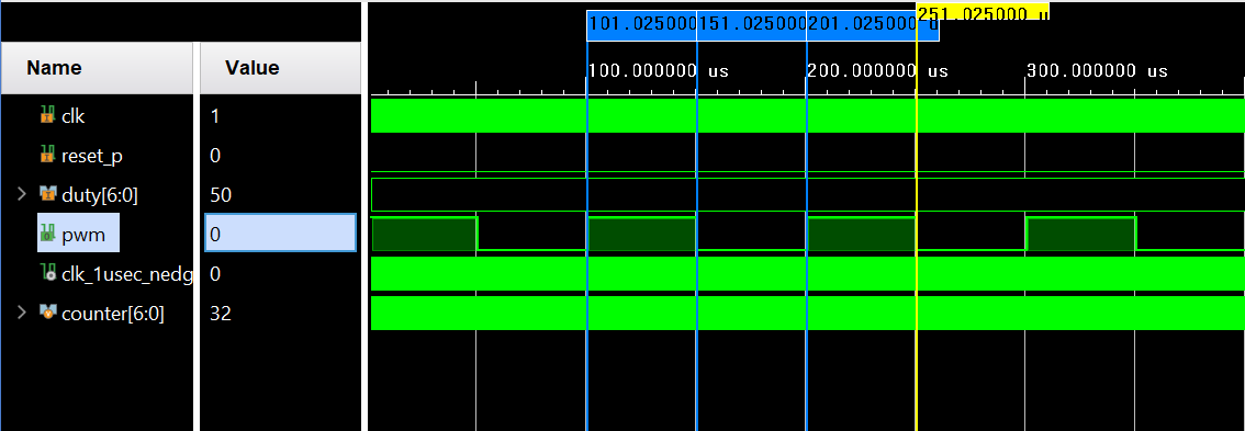
- 10kHz PWM 이기 때문에 주기는 100usec를 가지며, Duty ratio가 50이기 때문에 50usec 동안만 활성화 상태를 가지며, 50usec 동안은 비활성화 상태를 갖는다.
< Duty ratio = 75 >

- Positive edge는 101usec에서 발생했다면 Negative edge는 176usec에서 발생했다.
- 이를 통해 Duty ratio는 (176 - 101) / 100 = 75 임을 확인할 수 있다.
'RTL Design > Verilog 연습' 카테고리의 다른 글
| 10kHz인 PWM 설계 (Duty ratio stage 128단계) - (1) (0) | 2024.08.11 |
|---|---|
| DHT11 - 1 (0) | 2024.08.11 |
| 4X4 Matrix KeyPad - 2 (0) | 2024.08.10 |
| 4X4 Matrix KeyPad - 1 (0) | 2024.08.09 |
| Stop Watch - 1 (0) | 2024.08.07 |
'RTL Design/Verilog 연습' Related Articles
more
