
Notice
Recent Posts
Recent Comments
Link
| 일 | 월 | 화 | 수 | 목 | 금 | 토 |
|---|---|---|---|---|---|---|
| 1 | ||||||
| 2 | 3 | 4 | 5 | 6 | 7 | 8 |
| 9 | 10 | 11 | 12 | 13 | 14 | 15 |
| 16 | 17 | 18 | 19 | 20 | 21 | 22 |
| 23 | 24 | 25 | 26 | 27 | 28 | 29 |
| 30 |
Tags
- prescaling
- soc 설계
- vivado
- i2c 통신
- atmega 128a
- LED
- Linked List
- hc-sr04
- DHT11
- stop watch
- D Flip Flop
- java
- gpio
- dataflow modeling
- BASYS3
- ring counter
- FND
- Edge Detector
- behavioral modeling
- Recursion
- pwm
- half adder
- uart 통신
- test bench
- ATMEGA128A
- verilog
- structural modeling
- Algorithm
- KEYPAD
- Pspice
Archives
- Today
- Total
거북이처럼 천천히
Verilog RTL 설계(7월 12일 - 3, 동기식 카운터 - 2) 본문
1. Synchronous MOD-16 Up Counter implemented with T - Flip Flop
< Source >
// Behavioral modeling of T Flip Flop
module t_flip_flop (
    input t,
    input clk, enable, reset_p,
    output reg q);

    always @(posedge clk or posedge reset_p) begin
        if(reset_p) q = 0;
        else if(enable) q = (t)? ~q : q;
        else q = q;
    end
endmodule

// Synchronous MOD-16 Up Counter implemented with T Flip-Flop
module Synchronous_MOD_16_Up_Counter_T_Flip_Flop_Positive(
    input clk, enable, reset_p,
    output [3:0] count );

    wire temp_1, temp_2;

    t_flip_flop t_flip_flop0 (1, clk, enable, reset_p, count[0]);
    t_flip_flop t_flip_flop1 (count[0], clk, enable, reset_p, count[1]);

    and(temp_1, count[1], count[0]);

    t_flip_flop t_flip_flop2 (temp_1, clk, enable, reset_p, count[2]);

    and(temp_2, count[2], temp_1);

    t_flip_flop t_flip_flop3 (temp_2, clk, enable, reset_p, count[3]);

endmodule
< Simulation >

< RTL analysis >
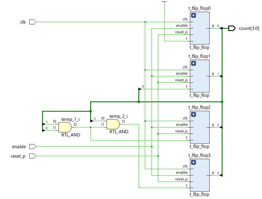
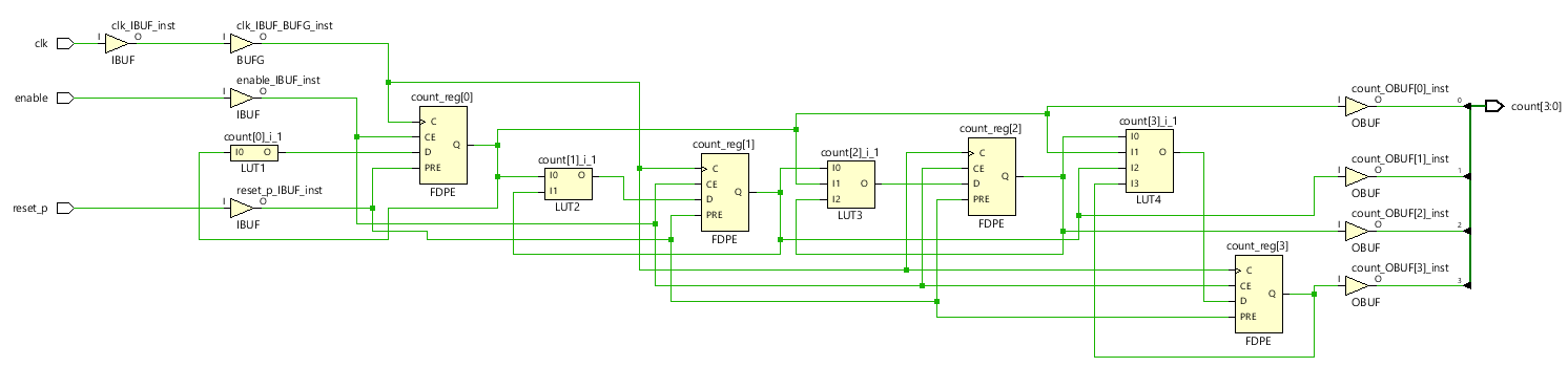
< Synthesis >

2. 왜 동기식 업 카운터를 D Flip - Flop으로 구현 했는가? T Flip - Flop으로 구현하면 안되는가?
- T Flip Flop을 기반으로 동기식 업 카운터를 설계한다면 다음과 같이 설계해야 할 것이다.
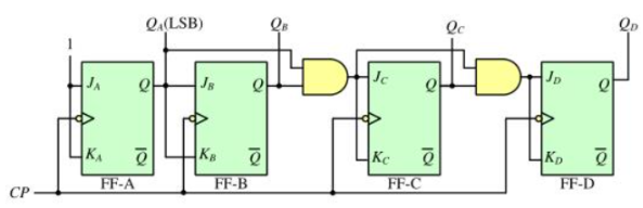
- FPGA는 D Flip Flop과 LUT (Look Up Table)을 갖고 있다.
- 따라서 T Flip Flop을 기반으로 동기식 업 카운터를 설계하기 위해서는 다음과 같은 과정이 필요하다.
- D Flip Flop을 기반으로 T Flip Flop을 만들기.
- T Flip Flop을 기반으로 동기식 업 카운터 만들기 - 위와 같은 과정으로 T Flip Flop을 기반으로 동기식 업 카운터을 설계하면 위와 소스 코드를 작성할 수 있다.
- 자. D Flip Flop을 기반으로 설계했을 때와 T Flip Flop을 기반으로 설계했을 때를 비교해보아라. 어떤가?
- D Flip Flop은 Dataflow modeling을 설계하기 때문에 단순히 덧셈을 통해 구현이 가능하지만,
- T Flip Flop은 T Flip Flop을 만든 뒤, 이를 Structural modeling으로 설계하기 때문에 각각의 wire를 연결해야한다.
- 즉, T Flip Flop을 기반으로 설계하는 것이 LUT을 덜 사용하여 효율적일 수 도 있지만, 시간 및 설계 편의성 측면에서 보면 D Flip Flop 으로 설계하는 것이 더 편하고, 빠르게 설계가 가능하다. - 따라서 상황에 맞게 설계하는 것이 중요하다.
- 하지만, D Flip Flop을 기반으로 동기식 카운터를 설계하는 것이 훨씬 빠르고, 편리하게 설계할 수 있다.
3. Synchronous MOD-16 Down counter implemented with D Flip Flop (Positive edge)
< Source >
// Synchronous MOD-16 Down counter implemented with D Flip Flop (Positive edge)
module Synchronous_MOD_16_Down_Counter_D_Flip_Flop_Positive(
    input clk, enable, reset_p,
    output reg [3:0] count );

    always @(posedge clk or posedge reset_p) begin
        if(reset_p) count = 15;
        else if(enable) count = count - 1;
        else count = count;
    end

endmodule- MOD-16 Down Counter 이기 때문에 15 ~ 0 까지 Down counting이 가능하며, 2진수로 1111를 표현하기 위해서는 출력 값은 4bit 크기를 가져야 한다.
- clk (Clock Pulse)가 Positive edge에서 down counting이 실행된다.
- D Flip Flop을 기반으로 counter를 설계하기 때문에 사칙 연산이 수행이 가능하며, 빠르고, 직관적으로 설계가능하다.
< Simulation >

- Positive edge에서 down counting이 발생함을 확인할 수 있다.
< RTL Analysis >

< Synthesis >
4. Synchronous MOD-16 Down counter implemented with D Flip Flop (Negative edge)
< Source >
// Synchronous MOD-16 Down counter implemented with D Flip Flop (Negative)
module Synchronous_MOD_16_Down_Counter_D_Flip_Flop_Negative(
    input clk, enable, reset_p,
    output reg [3:0] count );

    always @(negedge clk or posedge reset_p) begin
        if(reset_p) count = 15;
        else if(enable) count = count - 1;
        else count = count;
    end

endmodule
< Simulation >

- clk (Clock Pulse)가 Negative edge에서 down counting이 발생함을 확인할 수 있다.
< RTL Analysis >

< Synthesis >

'RTL Design > Verilog RTL 설계' 카테고리의 다른 글
| Verilog RTL 설계(7월 12일 - 5, 동기식 업/다운 카운터) (2) | 2024.07.14 |
|---|---|
| Verilog RTL 설계(7월 12일 - 4, 동기식 BCD 카운터) (2) | 2024.07.14 |
| Verilog RTL 설계(7월 12일 - 2, 동기식 카운터 - 1) (0) | 2024.07.13 |
| Verilog RTL 설계(7월 12일 - 1, 비동기 카운터까지 복습) (0) | 2024.07.13 |
| Verilog RTL 설계(6월 25일 - 3, Counter) (0) | 2024.06.29 |
'RTL Design/Verilog RTL 설계' Related Articles
more


