
Notice
Recent Posts
Recent Comments
Link
| 일 | 월 | 화 | 수 | 목 | 금 | 토 |
|---|---|---|---|---|---|---|
| 1 | ||||||
| 2 | 3 | 4 | 5 | 6 | 7 | 8 |
| 9 | 10 | 11 | 12 | 13 | 14 | 15 |
| 16 | 17 | 18 | 19 | 20 | 21 | 22 |
| 23 | 24 | 25 | 26 | 27 | 28 | 29 |
| 30 |
Tags
- LED
- soc 설계
- Algorithm
- stop watch
- uart 통신
- DHT11
- KEYPAD
- prescaling
- verilog
- atmega 128a
- BASYS3
- Edge Detector
- gpio
- ring counter
- vivado
- test bench
- Pspice
- behavioral modeling
- half adder
- hc-sr04
- FND
- i2c 통신
- dataflow modeling
- pwm
- Linked List
- java
- structural modeling
- Recursion
- D Flip Flop
- ATMEGA128A
Archives
- Today
- Total
거북이처럼 천천히
Verilog RTL 설계(7월 12일 - 4, 동기식 BCD 카운터) 본문
1. BCD code
- BCD (Binary coded decimal) code는 십진수로 표현된 값의 각 자리 수를 이진수로 표현하는 방법이다.
- ex) 십진수로 표현된 수인 10에 대해서 2진법으로 변환하면 A이지만, BCD 코드로 표현할 경우, 각 자리 수 1, 0을 각각 2진수로 변환하기 때문에 BCD 코드로 변환하면 0001 0000 으로 변환된다.
● Binary code : 10 → A
● BCD code : 10 → 0001 0000
1.1. BCD code의 장점
1) 10진수와 같은 수 체계를 사용하여 친숙하다.
- Binary code와 달리 10진수의 각 자리수를 이진화하기 때문에 10진수와 같은 수 체계를 사용하여 사용자에게 친숙하다.
2) BCD 변환기는 하드웨어적으로 구현하기 쉽다.
- BCD 변환기는 하드웨어 알고리즘적으로 구현하기 쉽다.
- 각자리마다 BCD 변환기를 갖고 있기 때문에 PDT가 적다.
3) 정확한 소수점 표현이 가능하다.
1.2. BCD Counter
- BCD Counter는 0 ~ 9까지 Counting이 가능한 Counter이다.
- BCD는 각 십진수의 자릿수를 4bit의 이진수로 표현하기 때문에 BCD counter는 0000 ~ 1001까지 Counting이 가능하다.
- 1010 ~ 1111 까지의 6개의 상태는 사용하지 않으며, 만약 해당 상태 값이 출력된다면 해당 출력값은 잘못된 출력값이다.
- BCD counter는 디지털 시계, 계측기 등 10진수 표시가 필요한 디지털 기기에 주로 사용된다.
2. Vivado를 사용한다면 손쉽게 논리회로를 설계할 수 있다.
- Vivado를 사용하지 않고, 동기식 BCD 업 카운터의 디지털 논리 회로를 설계한다면 1) State diagram을 그리고, 2) 카르노맵을 통해 논리식을 간소화, 3) 간소화된 논리식을 기반으로 디지털 논리회로 구성 을 해야할 것이다.
( Vivado을 사용하지 않고, 동기식 업 카운터를 설계하는 방법이 궁금하다면 아래 게시글을 참고)
https://jbhdeve.tistory.com/232
동기식 카운터 (Synchronous Counter)
1. 동기식 카운터 카운터를 구성하는 모든 플립플롭들은 클록 펄스 (Clock pulse)와 동기화되어 있는 카운터따라서 모든 플립플롭들은 클록 펄스의 변화에 대해서 동시에 동작한다.이러한 특징 때
jbhdeve.tistory.com
- 하지만, Vivado를 사용한다면 위와 같은 복잡한 과정없이 C언어로 코딩하듯 회로 설계가 가능하다.
3. Synchronous BCD Up Counter (Positive edge trigger)
< Source >
// Synchronous BCD Counter implemented with D Flip Flop (Positive)
module Synchronous_BCD_Up_Counter_implemented_with_D_Flip_Flop_Positive(
    input clk, enable, reset_p,
    output reg [3:0] count );

    always @(posedge clk or posedge reset_p) begin
        if(reset_p) count = 0;
        else if(enable) begin
            count = count + 1;
            if(count >= 10) count = 0;
        end
        else count = count;
    end

endmodule
< Simulation >

4. Advanced Synchronous BCD Up Counter (Positive edge trigger)
4.1. Ripple effect
- Counter가 Counting하는 과정에서 일시적으로 불안정한 출력값, 잘못된 출력값이 출력되는 현상을 의미한다.
- 위 Up Counting 과정을 보게 되면 count 값을 1씩 증가시키는 과정을 보게되면 1001 (9) + 0001 (1) = 1010 (A) 에서 일시적으로 count는 1010(A) 값을 갖게 된다.
- BCD Counter는 0000 ~ 1001 범위의 값만 가질 수 있기 때문에 이는 잘못된 값이다.
- 이처럼 Counting 과정에서 일시적으로 불안정한 출력값이 출력되는 현상을 "Ripple effect" 라한다.
- 따라서 이를 위한 대비책을 설계 및 준비할 필요가 있다.
4.2. Vivado를 통한 Advanced Synchronous BCD Up Counter (Positive edge trigger) 설계
< Source >
// Advanced Synchronous BCD Up Counter Implemented with D Flip Flop
module Advanced_Synchronous_BCD_Up_Counter_Implemented_With_D_Flip_Flop_Positive(
    input clk, enable, reset_p,
    output reg [3:0] count );

    always @(posedge clk or posedge reset_p) begin
        if(reset_p) count = 0;
        else if(enable) begin
            if(count >= 9) count = 0;
            else count = count + 1;
        end
        else count = count;
    end

endmodule- always 문을 보게 되면 if(count >= 9) count = 0; else count = count + 1; 처럼 코드를 수정했다.
- 즉, if(count >= 9) count = 0; 을 이용하여 count = 9에서 10으로 업 카운트되는 경우를 방지한다.
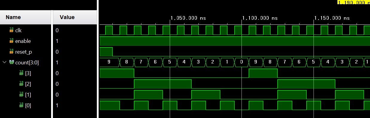
< Simulation >
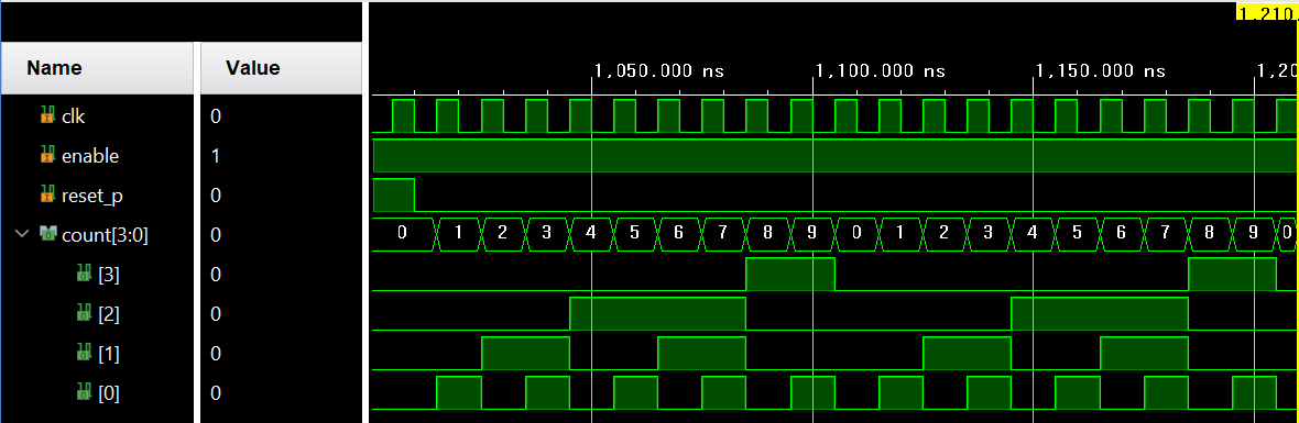
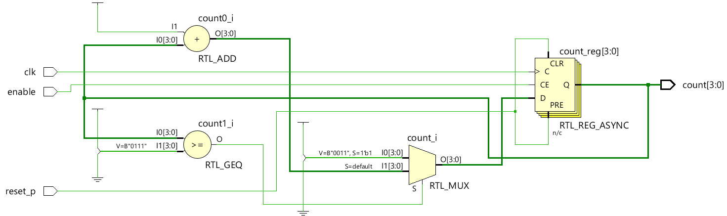
< RTL analysis >
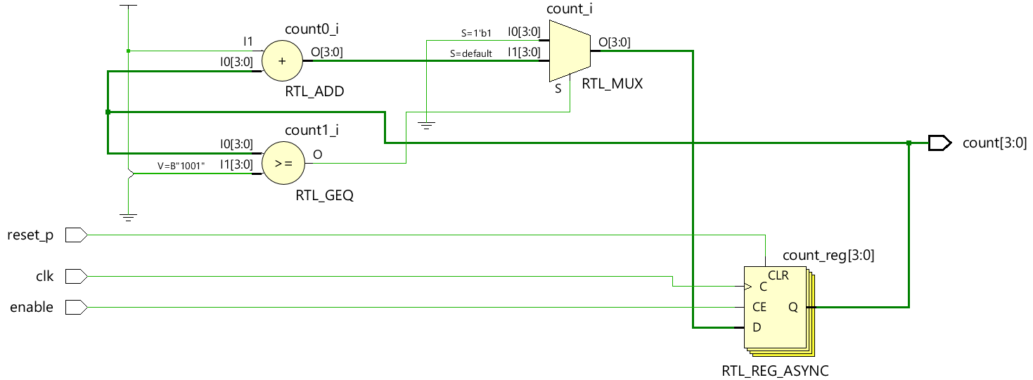
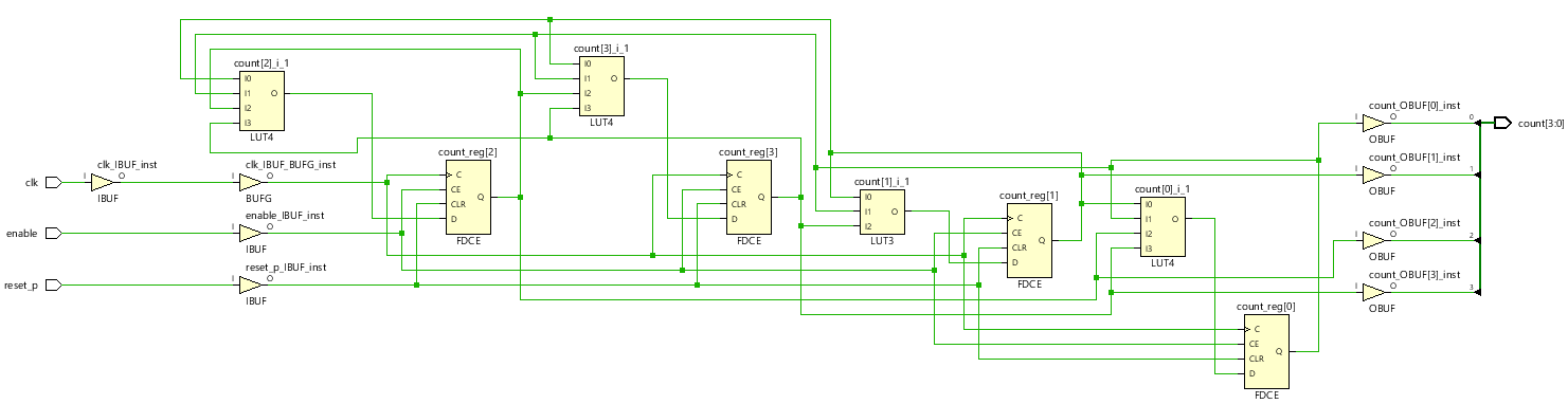
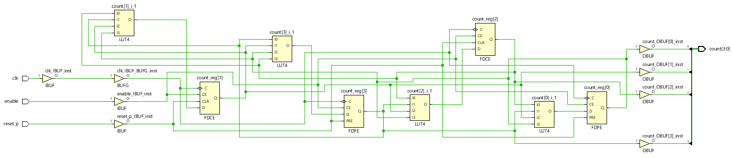
< Synthesis >
5. 3 ~ 7 까지만 Up counting이 가능한 동기식 BCD Up Counter
< Source >
// Sychronous 3 to 7 BCD Up Counter (Positive)
module Synchronous_Three_to_Seven_BCD_Up_Counter_Positive(
    input clk, enable, reset_p,
    output reg [3:0] count );

    always @(posedge clk or posedge reset_p) begin
        if(reset_p) count = 3;
        else if(enable) begin
            if(count>=7) count = 3;
            else count = count + 1;
        end
        else count = count;
    end

endmodule
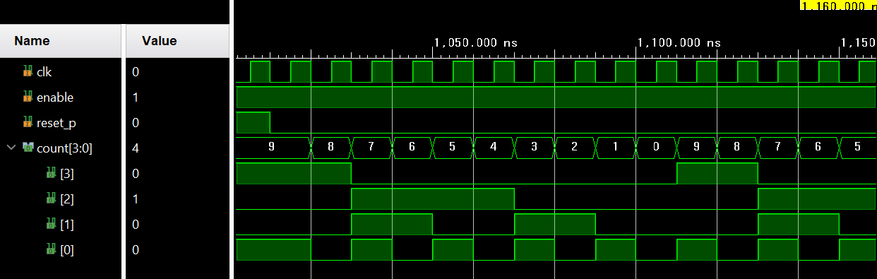
< Simulation >
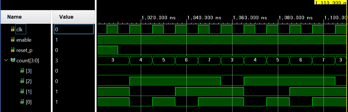
< RTL Analysis >
< Synthesis >

6. Synchronous BCD Down counter
< Source >
// Stchronous BCD Down Counter implemented with D Flip Flop (Positive)
module Synchronous_BCD_Down_Counter(
    input clk, enable, reset_p,
    output reg [3:0] count );

    always @(posedge clk or posedge reset_p) begin
        if(reset_p) count = 9;
        else if(enable) begin
            if(count <=0 ) count = 9;
            else count = count - 1;
        end
        else count = count;
    end

endmodule
< Simulation >
7. Advanced Synchronous BCD Down counter
- if(count <=0 ) count = 9; : 명령어를 통해 downflow 가 발생하면 다시 9로 초기화 시켜주지만,
만약에 1010(A) ~ 1111(F) 값을 갖는다면 해당 영역부터 9가 되기 까지 연속적으로 Ripple 현상이 발생할 것이다. - 이를 방지하기 위한 추가적인 조건이 필요하다.
- 물론 위 조건문으로도 위 상황을 방지할 수 있지만, The worst case를 고려하여 위와 같은 상황이 발생하면 이에 대한 처리를 조건문에 추가해줌으로서 보다 좋은 설계 및 Ripple 현상을 방지할 수 있다.
< Source >
// Advanced Synchronous BCD Down Counter implemented with D Flip Flop (Negative)
module Advanced_Synchronous_BCD_Down_Counter_Implemented_With_D_Flip_Flop_Negative(
    input clk, enable, reset_p,
    output reg [3:0] count );

    always @(negedge clk or posedge reset_p) begin
        if(reset_p) count = 9;
        else if(enable) begin
            if(count >= 10 | count <=0) count = 9;
            else count = count - 1;
        end
        else count = count;
    end
endmodule- clk (Clock Pulse)이 Negative edge에서 down counting이 동작한다.
- if(count >= 10 | count <=0) : count 값이 10보다 큰 경우에 대해서 count = 9이 되도록 설계함으로서 the worst case를 방지한다.
< Simulation >
< RTL analysis >

< Synthesis >
'RTL Design > Verilog RTL 설계' 카테고리의 다른 글
| Verilog RTL 설계(7월 12일 - 6, 링 카운터) (0) | 2024.07.14 |
|---|---|
| Verilog RTL 설계(7월 12일 - 5, 동기식 업/다운 카운터) (2) | 2024.07.14 |
| Verilog RTL 설계(7월 12일 - 3, 동기식 카운터 - 2) (2) | 2024.07.14 |
| Verilog RTL 설계(7월 12일 - 2, 동기식 카운터 - 1) (0) | 2024.07.13 |
| Verilog RTL 설계(7월 12일 - 1, 비동기 카운터까지 복습) (0) | 2024.07.13 |
'RTL Design/Verilog RTL 설계' Related Articles
more


