
Notice
Recent Posts
Recent Comments
Link
| 일 | 월 | 화 | 수 | 목 | 금 | 토 |
|---|---|---|---|---|---|---|
| 1 | ||||||
| 2 | 3 | 4 | 5 | 6 | 7 | 8 |
| 9 | 10 | 11 | 12 | 13 | 14 | 15 |
| 16 | 17 | 18 | 19 | 20 | 21 | 22 |
| 23 | 24 | 25 | 26 | 27 | 28 |
Tags
- Recursion
- DHT11
- i2c 통신
- ring counter
- verilog
- uart 통신
- stop watch
- FND
- ATMEGA128A
- dataflow modeling
- test bench
- hc-sr04
- gpio
- structural modeling
- BASYS3
- atmega 128a
- behavioral modeling
- Edge Detector
- soc 설계
- pwm
- LED
- Algorithm
- prescaling
- Pspice
- Linked List
- vivado
- half adder
- java
- KEYPAD
- D Flip Flop
Archives
- Today
- Total
거북이처럼 천천히
SR Latch / D Latch / D Flip Flop 본문
1. Behavioral modeling of SR Latch with clcok (Positive edge sensitive)
< Source code >
// Behavioral modeling of SR Latch
module Behavioral_modeling_of_SR_Latch_Positive_edge(
    input s, r,
    input clk, enable, reset,
    output reg q );

    always @(*) begin
        if(reset) q = 0;
        else if(enable) begin
            if(clk==1 && s==1 && r==0) q = 1;
            else if(clk==1 && s==0 && r==1) q = 0;
            else q =q;  end
        else q = q;
    end

endmodule
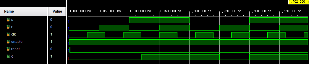
< Simulation >
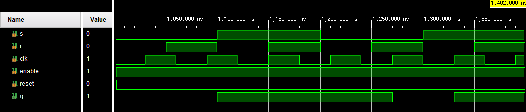
- clk = 1, s = 0, r = 0 일 경우, 이전 출력 값, q(t)을 유지한다.
- clk = 1, s = 1, r = 0 일 경우, 출력 값, q(t+1)을 1으로 set시킨다.
- clk = 1, s = 0, r = 1 일 경우, 출력 값, q(t+1)을 0으로 reset시킨다.
- clk = 1, s = 1, r = 1 일 경우, 이전 출력 값, q(t)을 유지한다.
- clk = 0 일 경우, 이전 출력 값, q(t)을 유지한다.
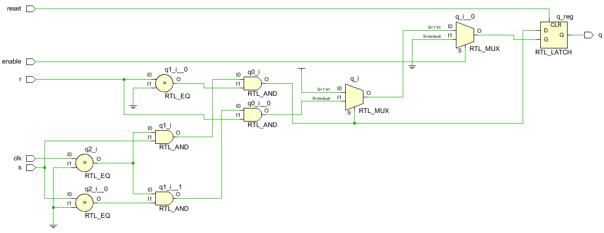
< RTL analysis >

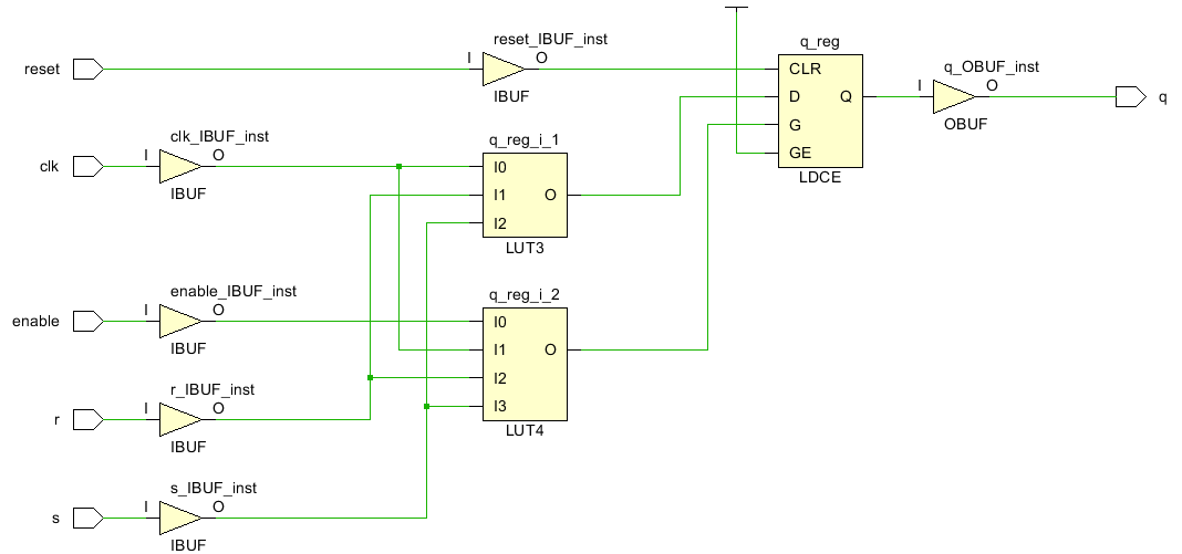
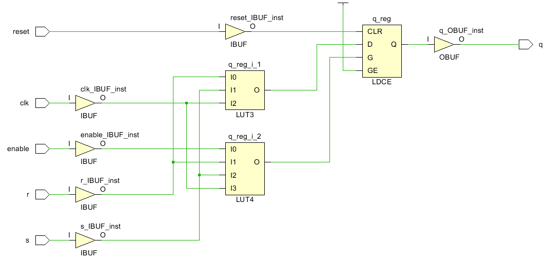
< Synthesis >
2. Behavioral modeling of SR Latch with clcok (Negative edge sensitive)
< Source code >
// Behavioral modeling of SR Latch
module Behavioral_modeling_of_SR_Latch_Negative_edge(
    input s, r,
    input clk, enable, reset,
    output reg q );

    always @(*) begin
        if(reset) q = 0;
        else if(enable) begin
            if(clk == 0 && s == 1 && r == 0) q = 1;
            else if(clk == 0 && s == 0 && r == 1) q = 0;
            else q = q;
        end
        else q = q;
    end

endmodule
< Simulation >
- clk = 0, s = 0, r = 0 일 경우, 이전 출력 값, q(t)을 유지한다.
- clk = 0, s = 1, r = 0 일 경우, 출력 값, q(t+1)을 1으로 set시킨다.
- clk = 0, s = 0, r = 1 일 경우, 출력 값, q(t+1)을 0으로 reset시킨다.
- clk = 0, s = 1, r = 1 일 경우, 이전 출력 값, q(t)을 유지한다.
- clk = 1 일 경우, 이전 출력 값, q(t)을 유지한다.
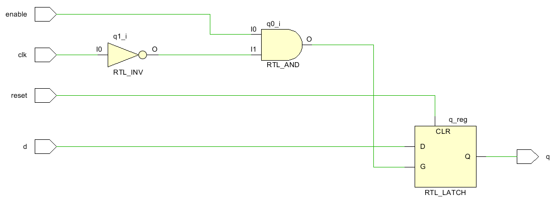
< RTL analysis >
< Synthesis >
3. Behavioral modeling of D Latch (Positive edge sensitive)
< Source code >
// Behavioral modeling of D Latch
module Behavioral_modeling_of_D_Latch_Positive_edge(
    input d,
    input clk, enable, reset,
    output reg q  );

    always @(*) begin
        if(reset) q = 0;
        else if(enable) begin
            if(clk == 1) q = d;
            else q = q;
        end
        else q = q;
    end

endmodule
< Simulation >
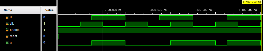
- clk = 1 인 경우, 출력 값, q(t+1)은 입력 값, d을 그대로 출력한다.
- clk = 0 인 경우, 이전 출력 값, q(t)을 그래로 출력한다.
< RTL analysis >
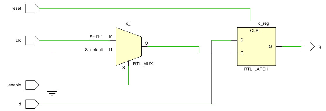
< Synthesis >

4. Behavioral modeling of D Latch (Negative edge sensitive)
< Source code >
// Behavioral modeling of D Latch
module Behavioral_modeling_of_D_Latch_Negative_edge(
    input d,
    input clk, enable, reset,
    output reg q  );

    always @(*) begin
        if(reset) q = 0;
        else if(enable && !clk ) q = d;
        else q = q;
    end

endmodule
< Simulation >

< RTL analysis >
< Synthesis >
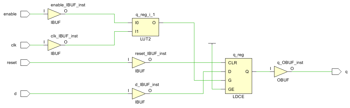
5. Behavioral modeling of D Flip Flop (Positive edge sensitive)
< Source code >
// Behavioral modeling of d flip flop (Positive edge)
module Behaviroal_Modeling_of_D_Flip_Flop_Positive_edge(
    input d,
    input clk, enable, reset,
    output reg q );

    always @(posedge clk or posedge reset) begin
        if(reset) q = 0;
        else if(enable) q = d;
    end

endmodule
< Simulation >
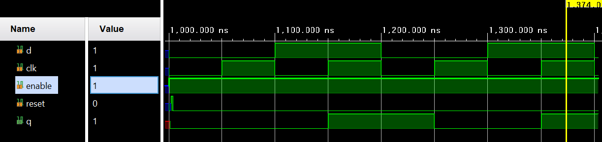
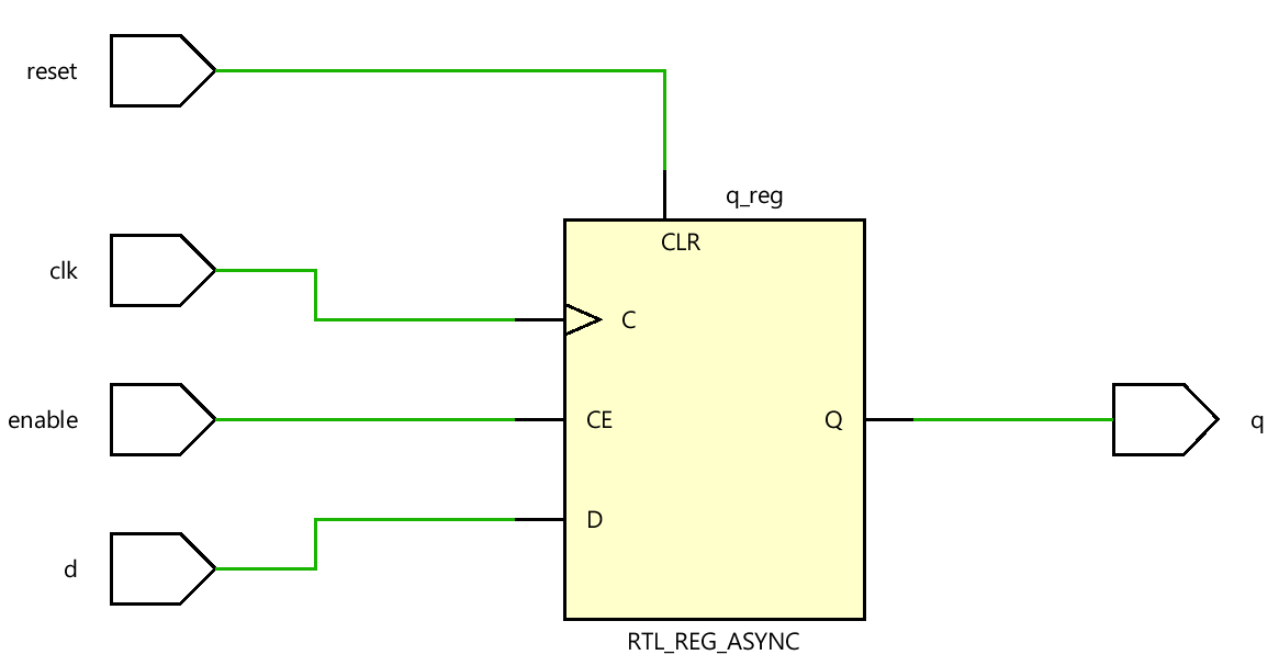
< RTL analysis >
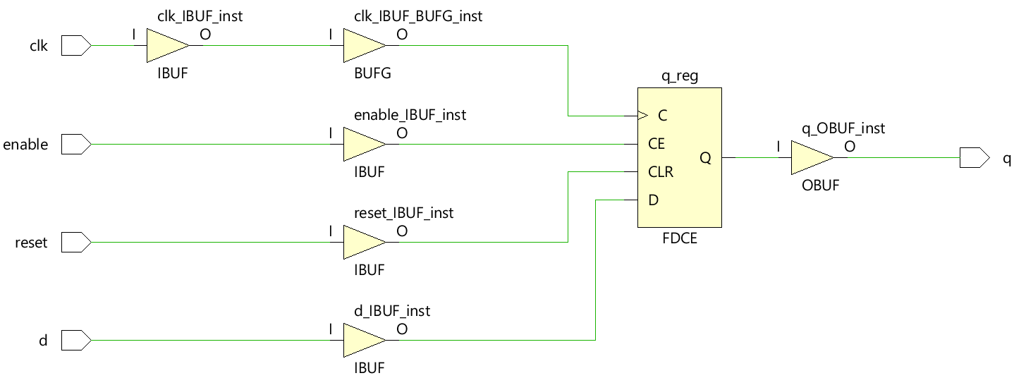
< Synthesis >
6. Behavioral modeling of D Flip Flop (Negative edge sensitive)
< Source code >
// Behavioraal modeling of D Flip Flop (Negative edge)
module Behavioral_Modeling_of_D_Flip_Flop_Negative_edge(
    input d,
    input clk, enable, reset,
    output reg q );

    always @(negedge clk or posedge reset) begin
        if(reset) q = 0;
        else if(enable) q = d;
    end

endmodule
< Simulation >

< RTL analysis >

< Synthesis >

'RTL Design > Verilog 연습' 카테고리의 다른 글
| T Flip Flop (0) | 2024.07.11 |
|---|---|
| JK Flip Flop (0) | 2024.07.11 |
| 4 X 1 MUX와 4 X 1 DEMUX의 조합 (0) | 2024.07.09 |
| 4 X 1 MUX / 1 X 4 DEMUX (0) | 2024.07.08 |
| Verilog 연습 리스트 (0) | 2024.07.07 |
'RTL Design/Verilog 연습' Related Articles
more


