
Notice
Recent Posts
Recent Comments
Link
| 일 | 월 | 화 | 수 | 목 | 금 | 토 |
|---|---|---|---|---|---|---|
| 1 | 2 | 3 | 4 | 5 | 6 | |
| 7 | 8 | 9 | 10 | 11 | 12 | 13 |
| 14 | 15 | 16 | 17 | 18 | 19 | 20 |
| 21 | 22 | 23 | 24 | 25 | 26 | 27 |
| 28 | 29 | 30 | 31 |
Tags
- FND
- dataflow modeling
- Linked List
- soc 설계
- uart 통신
- LED
- atmega 128a
- stop watch
- vivado
- test bench
- hc-sr04
- ring counter
- Recursion
- BASYS3
- ATMEGA128A
- DHT11
- i2c 통신
- java
- gpio
- verilog
- structural modeling
- Pspice
- pwm
- Edge Detector
- behavioral modeling
- Algorithm
- D Flip Flop
- KEYPAD
- half adder
- prescaling
Archives
- Today
- Total
거북이처럼 천천히
2024년 6월 12일 - Verilog Review 본문
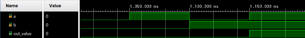
1. AND Gate (Behavior modeling)
- Behavior modeling을 통해 AND Gate를 구현
- < Source code>
// AND Gate Behavior Modeling
module AND_Gate_Behavior_Modeling(
        input a, b,
        output reg out_value);

        // input port a, b에 대해서
        // 입력 값에 따라 출력 값을 지정함으로서
        // 입/출력 값으로 회로를 설계했기 때문에
        // 이는 Behavior Modeling이다.
        always @(a ,b) begin
            case({a, b})
                2'b00 : out_value = 0;
                2'b01 : out_value = 0;
                2'b10 : out_value = 0;
                2'b11 : out_value = 1;
            endcase
        end
endmodule
- <Simulation result>

2. Half adder (Behavior Modeling)
- Half adder를 Behavior Modeling로 구현
- < Source code >
// Half adder behavior modeling
module Half_adder_Behavior_Modeling (
    input a, b,
    output reg carry, sum );

    // input port a, b에 대해서 a, b의 값에 따라
    // output port carry, sum의 값을 정의했기 때문에
    // 즉, 입/출력 값(Truth table)을 통해서 논리회로를 구현 했기 때문에
    // 이 Modeling은 behavior modeling이다.
    always @(a, b) begin
        case({a, b})
            2'b00 : begin carry = 0; sum = 0; end
            2'b01 : begin carry = 0; sum = 1; end
            2'b10 : begin carry = 0; sum = 1; end
            2'b11 : begin carry = 1; sum = 0; end
        endcase
    end

 endmodule
- <Simulation result >

3. Half adder (Structure Modeling)
- 논리 회로를 구성하는 논리 소자 관점에서 세세하게 논리 소자들 간에 연결을 정의하며, 회로를 구현하는 방법을 의미한다.
- 이미 XOR, AND 게이트는 라이브러리로 이미 구현되어 있기 때문에 따로 XOR, AND Gate의 Module를 구현 할 필요가 없다.
- 하지만, Module에 대한 공부를 위해 직접 구현도 해보자.
3.1. Half adder (Structure Modeling - By using library)
- < Source code >
// Structure modeling of half adder
module Half_adder_Structure_Modeling (
    input a, b,
    output carry, sum );

    // XOR library gate 사용
    xor(sum, a, b);

    // Gate library gate 사용
    and(carry, a, b);

endmodule
- < Simulation result >
3.2. Half adder (Structure Modeling)
- < Source code >
// AND Gate 의 Behavior Modeling
module AND_Gate (
    input a, b,
    output reg outputValue );

    always @(a, b) begin
        case({a, b})
            2'b 00 : outputValue = 0;
            2'b 01 : outputValue = 0;
            2'b 10 : outputValue = 0;
            2'b 11 : outputValue = 1;
         endcase
    end

endmodule

// XOR Gate 의 Behavior Modeling
module XOR_Gate (
    input a, b,
    output reg outputValue );

    always @(a, b) begin
        case({a, b})
            2'b 00 : outputValue = 0;
            2'b 01 : outputValue = 0;
            2'b 10 : outputValue = 0;
            2'b 11 : outputValue = 1;
         endcase
     end
endmodule

// Half adder Strutural Modeling
module Half_adder_Structure_Modeling_2(
    input a, b,
    output sum, carry);

    // Module을 통해 Instance를 초기화하는 과정에서
    // 입력부터 출력까지 순서를 지키면서 초기화를 한다면
    // . 키워드를 통해 초기화해줄 필요 없다.
    AND_Gate and_gate (a, b, carry);
    XOR_Gate xor_gate (.a(a), .b(b), .outputValue(sum));
- < Simulation result >

4. Half adder의 Dataflow Modeling
- Half adder를 Dataflow Modeling으로 구현
- < Source code >
module Half_adder_Data_Flow_Modeling (
    input a, b,
    output sum, carry );

    // Initialization about Wire
    // 출력 wire와 외부 모듈과의 Interface를 위해 wire 자료형으로 설정
    // result_half_adder는 2bit 크기를 갖는 wire 자료형 변수이다.
    wire[1:0] result_half_adder;

    // result_half_adder 변수에 half adder의 연산 결과 저장
    assign result_half_adder = a + b;

    // a + b 에서 +는 단순한 연산자가 아니라 덧셈 회로를 이용하여 연산하겠음을 의미
    // 덧셈 연산의 결과를 result_half_adder에 저장되면
    // 2비트 배열 형태로 저장되며, bit 0 = sum, bit 1 = carry가 저장
    assign sum = result_half_adder[0];
    assign carry = result_half_adder[1];

endmodule
- < Simulation result >

'RTL Design > Verilog 연습' 카테고리의 다른 글
| 1 bit Comparator (0) | 2024.06.30 |
|---|---|
| 4 bit parallel adder / subtractor (0) | 2024.06.30 |
| 4 bit parallel adder (0) | 2024.06.30 |
| Full adder (0) | 2024.06.29 |
| Half adder (0) | 2024.06.29 |
'RTL Design/Verilog 연습' Related Articles
more


