Notice
Recent Posts
Recent Comments
Link
| 일 | 월 | 화 | 수 | 목 | 금 | 토 |
|---|---|---|---|---|---|---|
| 1 | 2 | 3 | 4 | 5 | 6 | |
| 7 | 8 | 9 | 10 | 11 | 12 | 13 |
| 14 | 15 | 16 | 17 | 18 | 19 | 20 |
| 21 | 22 | 23 | 24 | 25 | 26 | 27 |
| 28 | 29 | 30 | 31 |
Tags
- vivado
- D Flip Flop
- stop watch
- java
- gpio
- DHT11
- LED
- atmega 128a
- Linked List
- Pspice
- uart 통신
- ring counter
- Edge Detector
- dataflow modeling
- pwm
- prescaling
- structural modeling
- half adder
- ATMEGA128A
- hc-sr04
- BASYS3
- i2c 통신
- Recursion
- Algorithm
- KEYPAD
- soc 설계
- verilog
- FND
- behavioral modeling
- test bench
Archives
- Today
- Total
거북이처럼 천천히
Full adder 본문
1. Behavioral Modeling of Full adder
<Source>
// Behavioral modeling of Full adder
module Full_adder_Behavioral_Modeling (
    input a, b, Cin,
    output reg sum, carry);

    always @(*) begin
        case({a, b, Cin})
            3'b000 : begin sum = 0; carry = 0; end
            3'b001 : begin sum = 1; carry = 0; end
            3'b010 : begin sum = 1; carry = 0; end
            3'b011 : begin sum = 0; carry = 1; end
            3'b100:  begin sum = 1; carry = 0; end
            3'b101 : begin sum = 0; carry = 1; end
            3'b110 : begin sum = 0; carry = 1; end
            3'b111 : begin sum = 1; carry = 1; end
        endcase
    end

endmodule
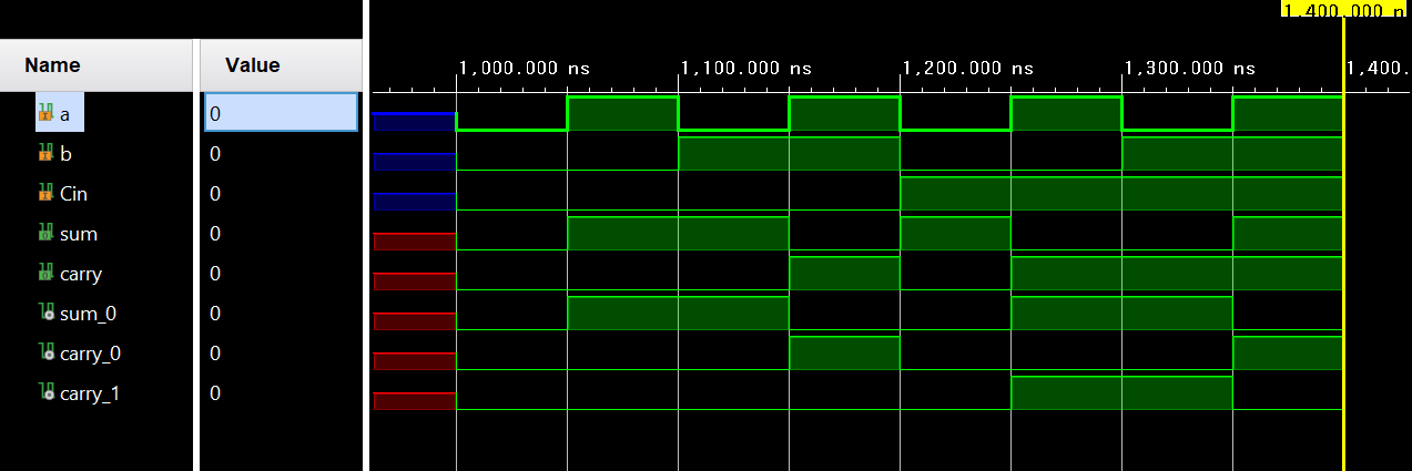
<Simulation>

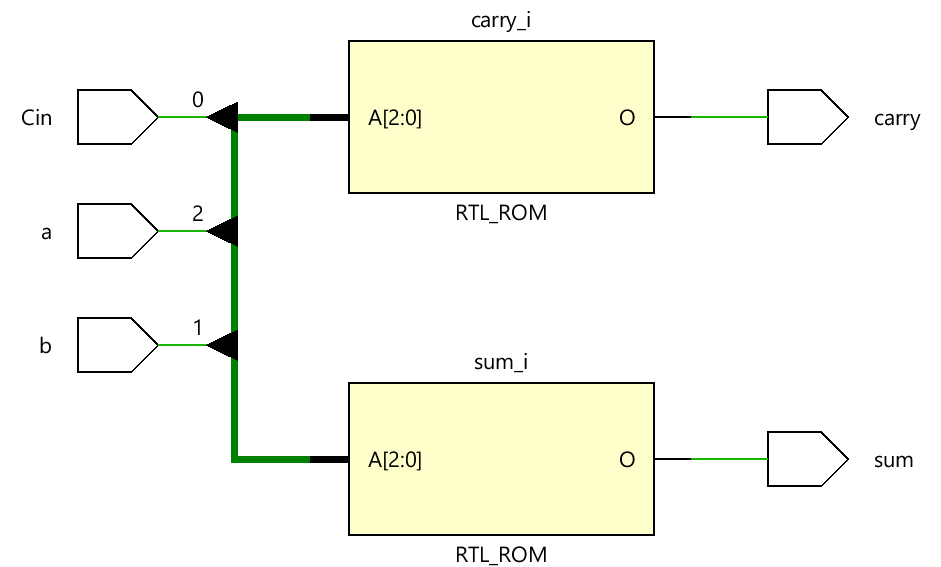
<RTL Analysis>

<Synthesis>

2. Structural Modeling of Full adder
<Source>
// Behavioral modeling of and gate.
module and_gate (
    input a, b,
    output reg out);

    always @(a, b) begin
        case({a, b})
            2'b00 : out = 0;
            2'b01 : out = 0;
            2'b10 : out = 0;
            2'b11 : out = 1;
        endcase
    end
endmodule

// Behavioral modeling of xor gate.
module xor_gate (
    input a, b,
    output reg out);

    always @(a, b) begin
        case({a, b})
            2'b00 : out = 0;
            2'b01 : out = 1;
            2'b10 : out = 1;
            2'b11 : out = 0;
        endcase
    end
 endmodule

// Behavioral modeling of or gate.
module or_gate (
    input a, b,
    output reg out);

    always @(a, b) begin
        case({a, b})
            2'b00 : out = 0;
            2'b01 : out = 1;
            2'b10 : out = 1;
            2'b11 : out = 1;
        endcase
    end
endmodule

// Structural modeling of half adder
module half_adder_Structural_Modeling (
    input a, b,
    output sum, carry);

    and_gate and0 (a, b, carry);
    xor_gate xor0 (a, b, sum);

endmodule

// Structural modeling of Full adder
module Full_adder_Structural_Modeling(
    input a, b, Cin,
    output sum, carry);

    wire sum_0, carry_0, carry_1;

    half_adder_Structural_Modeling half0 (a, b, sum_0, carry_0);
    half_adder_Structural_Modeling half1 (Cin, sum_0, sum, carry_1);

    or_gate or0 (carry_0, carry_1, carry);


endmodule
<Simulation>

<RTL Analysis>

<Synthesis>

3. Dataflow Modeling of Full adder
<Source>
module Full_adder_Dataflow_Modeling(
    input a, b, Cin,
    output sum, carry );

    wire[1:0] result = a + b + Cin;

    assign sum = result[0];
    assign carry = result[1];

endmodule
<Simulation>

<RTL Analysis>

<Synthesis>

'RTL Design > Verilog 연습' 카테고리의 다른 글
| 1 bit Comparator (0) | 2024.06.30 |
|---|---|
| 4 bit parallel adder / subtractor (0) | 2024.06.30 |
| 4 bit parallel adder (0) | 2024.06.30 |
| Half adder (0) | 2024.06.29 |
| 2024년 6월 12일 - Verilog Review (1) | 2024.06.13 |


